


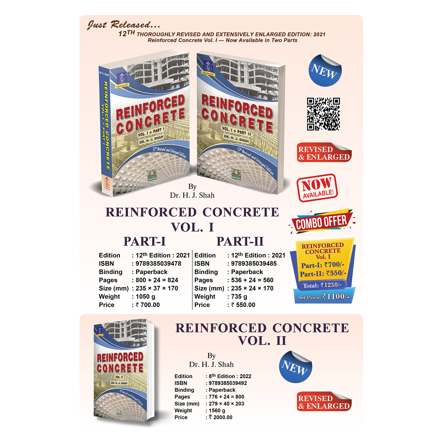
Reinforced Concrete Vol. I (Part I & Part II ) By Dr. H. J. Shah
₹990.00
Reinforced Concrete Vol. I – Part I
By Dr. H. J. Shah
12th Edition 2021
ISBN : 9789385039478
Binding : Paperback
Pages : 800 + 24 = 824
Size (mm) : 235 × 37 × 170
Weight : 1050 g
Price : ₹ 700.00
Reinforced Concrete Vol. I – Part II
By Dr. H. J. Shah
12th Edition 2021
ISBN : 9789385039485
Binding : Paperback
Pages : 536 + 24 = 560
Size (mm) : 235 × 24 × 170
Weight : 735 g
Price : ₹ 550.00
Out of stock
CompareDescription
|
This book presents the basic principles involved in Analysis and Design of Reinforced Concrete Structures. This 12th edition of Vol. I has been thoroughly revised and extensively enlarged in two parts. Almost all chapters are revised with adding a plenty of new matter, examples and figures. Mix design as per latest IS:10262 with excel programs is added. A number of excel programs have been added to clarify the subject matter and design the elements of structure. As per prevailing market conditions the default combination of materials is revised to M20 grade concrete and Fe 500 grade steel, however, the other combinations of materials have not been completely ignored. The outline of the book “Reinforced Concrete Vol. I – Part I” is as mentioned below: Chapter 1 to 3 discuss mainly Concrete Technology. Chapter 1 introduces the subject, while Now this book “Reinforced Concrete Vol. I – Part I”, in its 16 Chapters and Appendix contains: * 350 Neatly drawn sketches |
The outline of the book “Reinforced Concrete Vol. I – Part II” is as mentioned below: Chapter 17 contains design of columns used in framed structures. The design interaction diagrams are derived and excel program is prepared for rectangular columns. Now this book “Reinforced Concrete Vol. I – Part II”, in its 14 Chapters and Appendix contains: * 261 Neatly drawn sketches The book in the present form will prove to be extremely useful to the students preparing for the Degree examinations in Civil Engineering and Architecture of all the Indian Universities, Diploma examinations conducted by various Boards of Technical Education, Certificate Courses as well as for the A.M.I.E., U.P.S.C., G.A.T.E., I.E.S., and other similar competitive and professional examinations. It should also be an immense use to practicing Civil Engineers. |
Additional information
| Author Name | |
|---|---|
| Book Edition | |
| ISBN | |
| Book Binding | |
| Pages | |
| Size | |
| Weight | |
| Old ISBN | 8185594546, 9788185594743, 9788192869247, 9789380358000, 9789380358475, 9789385039188 |
Details Content
PART 1
1 : INTRODUCTION
2 : PROPERTIES OF INGREDIENTS OF CONCRETE
3 : STRUCTURAL CONCRETE
4 : DESIGN FOR FLEXURE: FUNDAMENTALS
5 : DESIGN FOR FLEXURE
6 : LIMIT STATE METHOD
7 : SHEAR AND DEVELOPMENT LENGTH
8 : DEFLECTION AND CRACKING
9 : SIMPLY SUPPORTED AND
10 : SIMPLY SUPPORTED AND
11 : CONTINUOUS BEAMS AND SLABS
12 : TORSION
13 : STAIRS
14 : LOAD CALCULATIONS FOR
15 : SIMPLE DESIGNS
16 : FRAMED BEAMS
APPENDIX A : SHORT QUESTIONS WITH ANSWERS
APPENDIX B : USEFUL TABLE
INDEX
PART 1
Chapter 1 INTRODUCTION
1-1. Structural design—Role of a structural engineer
1-2. Concrete and reinforced concrete
1-3. Mechanics of reinforce concrete
1-4. Advantages and limitations of using concrete
1-5. Structural elements
(1) Slabs
(2) Beams
(3) Columns
(4) Walls
(5) Foundations
1-6. Loads on structure
(1) Dead loads
(2) Live loads
(3) Impact loads
(4) Wind loads
(5) Earthquake loads
(6) Longitudinal loads
1-7. Load combinations
1-8. Ductility versus brittleness
1-9. Strength and serviceability
1-10. Response of a structure to wind and earthquake loads
1-11. Ordinary and ductile structures
1-12. Methods of design
(1) Working stress method
(2) Limit state method
1-13. Codes of practice
1-14. Adaptation of SI units
1-15. Presentation of design calculation of a project
QUESTIONS I
Chapter 2 PROPERTIES OF INGREDIENTS OF CONCRETE
2-1. Introductory
Cement
2-2. General
2-3. Manufacture of Portland cement
2-4. Basic chemistry of cement
(1) Lime
(2) Silica
(3) Alumina
(4) Iron oxide
(5) Magnesia
(6) Calcium sulphate
(7) Alkalis
(8) Sulphur trioxide
Properties of chemical compounds
2-5. Chemical properties of cement
(1) Lime saturation factor
(2) Ratio of alumina to iron oxide
(3) Insoluble residue
(4) Magnesia
(5) Total sulphate content as sulphuric anhydride
(6) Total loss in ignition
2-6. Hydration of cement
(1) General
(2) Chemistry of hydration
(3) Heat of hydration and strength
(4) Rate of hydration
2-7. Types of cement
(1) Ordinary portland cement
(2) Rapid hardening cement
(3) Blast furnace slag portland cement
(4) Portland pozzolana cement
(5) Hydrophobic cement
(6) Low heat portland cement
(7) Sulphate resisting cement
(8) High alumina cement
(9) Super-sulphated cement
(10) Oil-well cement
(11) Ultra-rapid hardening portland cement
(12) White cement
(13) Coloured cement
(14) Water-proof portland cement
(15) Masonry cement
(16) Expanding cement
(17) Quick setting cement
(18) Air-entraining cement
2-8. Selection of cement for production of concrete
2-9. Tests for cement
2-10. Fineness test
(1) By dry sieving
(2) Blain air permeability method
2-11. Consistency of standard
Cement paste
Procedure
2-12. Test for setting times
Procedure
False set
2-13. Soundness test
Procedure
2-14. Autoclave expansion
Procedure
2-15. Density test
Apparatus
Materials
Procedure
Calculation
Specific gravity of cement
2-16. Test for compressive strength
2-17. Heat of hydration test
2-18. Storing of cement
Mineral admixtures
2-19. Mineral admixtures
(1) Pozzolana
(2) Ground granulated blast furnace slag
AGGREGATES
2-20. Introductory
2-21. Aggregate size
(1) Single size aggregate
(2) Graded aggregates
2-22. Fine and coarse aggregate
2-23. Properties of aggregate
2-23-1. Particle shape
2-23-2. Surface texture
2-23-3. Strength of aggregate
(1) Compressive strength of prepared samples of parent rocks
(2) Aggregate crushing value
(3) Ten percent fines value
(4) Aggregate impact value
2-23-4. Specific gravity
(1) Apparent specific gravity
(2) Specific gravity based on saturated surface dry basis
2-23-5. Bulk density
2-23-6. Water absorption and surface moisture
(1) Water absorption
PART 1
(2) Surface moisture
2-23-7. Bulking of sand
2-23-8. Deleterious substances in aggregates
(1) Organic impurities
(2) Surface coatings
(3) Salt contamination
(4) Weak or unsound particles
2-23-9. Soundness of aggregate
2-23-10. Alkali-aggregate reaction
2-24. Sieve analysis
Fineness modulus
2-25. Standard grading
(1) Coarse aggregate
(2) Fine aggregate
(3) All-in-aggregate
2-26. Use of grading curves
(1) Coarse aggregates
(2) Fine aggregates
WATER
2-37. Water for mixing concrete
2-28. Water-cement ratio and water-cementitious materials ratio
CHEMICAL ADMIXTURES
2-29. Admixtures
(1) Accelerators
(2) Retarders
(3) Water reducing admixtures
(4) Air-entraining agents
REINFORCEMENT
2-30. Steel as reinforcement
2-31. Types of reinforcement
(1) Plain bars
(2) High strength deformed (hsd) bars
2-31-1. Plain bars
(1) Mild steel bars
(2) Medium tensile steel bars
(3) Hard drawn wire or welded wire fabric
2-31-2. High strength deformed (hsd) bars
(1) Cold twisted deformed (ctd) bars
(2) Thermo-mechanically treated (tmt) bars
2-32. Corrosion–resistant steel
2-33. Grades of normal and enhanced quality
Hsd rebars for reinforced concrete
2-34. Bending and fixing of bars
2-35. Welding of reinforcement
2-36. General notes for site engineers
QUESTIONS II
EXAMPLES II
Chapter 3 STRUCTURAL CONCRETE
3-1. Proportioning of ingredients
(1) Design mix concrete
(2) Nominal mix concrete
Dosage of admixtures
3-2. Estimation of materials for nominal mix
3-3. Measurement of materials
(1) Mass-batching
(2) Volume-batching
3-4. Mixing and placing of concrete
(1) Batch mixers
(2) Ready mix concrete (rmc)
(3) Continuous mixers
3-5. Compaction
3-6. Curing
(1) Moist curing
(2) Membrane curing
(3) Steam curing
3-7. Formwork for R.C.C. members
3-8. Workability
(1) Slump test
(2) Compacting factor test
(3) Vee-bee test
3-9. Factors influencing workability
3-10. Strength of concrete and water-cement ratio
(1) Compaction
(2) Curing
(3) Fineness of aggregate
(4) Fatigue and impact
(5) Age
(6) Compressive strength of cement and concrete
3-11. Compressive strength of concrete
(1) Object
(2) Equipments
(3) Preparation
(4) Capping
(5) Testing
(6) Results
3-12. Tensile strength of concrete
(1) Split cylinder test
(2) Standard beam test — modulus of rupture test
3-13. Non-destructive tests
(1) Rebound hardness test
(2) Ultrasonic pulse velocity test
3-14. Stress-strain behaviour of concrete under short term loads
(1) Compressive loads
(2) Tensile loads
3-15. Short term static modulus of elasticity
Poisson’s ratio
3-16. Shrinkage
(1) Plastic shrinkage
(2) Drying shrinkage
(3) Carbonation shrinkage
(4) Autogenous shrinkage
3-17. Creep
3-18. Durability of concrete
(1) Use of inferior quality materials
(2) Improper compaction and curing
(3) Limits on cement content
(4) Requirements of concrete cover to steel reinforcement
(5) Improper design and detailing
3-19. Temperature change
3-20. Concrete quality control
3-21. Sampling and strength tests of concrete
(1) Sampling and frequency of sampling
(2) Strength tests
(3) Preparing sampling and testing records
(4) Checking the record
(5) Analyse the results
3-22. Statistical analysis of test results
(1) Density function
(2) Normal distribution
(3) Mean
(4) Standard deviation
3-23. Standard deviation
(1) Standard deviation based on test strength of sample
(2) Assumed standard deviation
PART 1
3-24. Acceptance criteria
Design mix concrete
3-25. Introductory
3-26. Use of plasticizers and super-plasticizers
Efficiency of super plasticizer
Mix design for ordinary and
Standard grades of concrete
3-27. Basic assumptions
3-28. Data for mix design
3-29. Target strength for mix design
3-30. Assumed standard deviation
3-31. Selection of water-cement/
Water-cementitious materials ratio
Portland pozzolana cement
3-32. Estimation of air content
3-33. Selection of water content and admixture content
Note for site work
Type of aggregates
Workability required
Use of chemical admixtures
3-34. Calculation of cement/cementitious materials content
3-35. Estimation of coarse and fine aggregate
Proportion in all–in aggregates
Correction for w/c ratio
Correction for concrete of increased workability
3-36. Estimation of masses of various ingredients
3-37. Trial mixes
QUESTIONS 3
EXAMPLES 3
Chapter 4 DESIGN FOR FLEXURE: FUNDAMENTALS,
4-1. Introductory
4-2. Review of theory of simple bending
4-3. Practical requirements of an r.C.C. Beam
4-4. Size of the beam
4-5. Cover to the reinforcement
4-6. Spacing of bars
4-7. Design requirements of a beam
4-8. Classification of beams
(1) Singly reinforced and doubly reinforced beams
(2) Rectangular and flanged beams
4-9. Effective width of a flanged beam
4-10. Cracking moment
4-11. Balanced, under-reinforced and over-reinforced design
(1) Balanced design
(2) Under-reinforced design
(3) Over-reinforced design
4-12. Bending of an r.C.C. Beam
(1) Uncracked concrete stage
(2) Concrete cracked-elastic stresses stage
(3) Ultimate strength stage
4-13. Design methods
Chapter 5 DESIGN FOR FLEXURE: WORKING STRESS
METHOD
5-1. Permissible stresses
Increase in permissible stresses
5-2. Modular ratio
5-3. Design for flexure–assumptions
Singly reinforced beams
5-4. Derivation of formulae for balanced design
5-5. Transformed area method
(1) To decide the type of the beam
(2) Balanced design
(3) Over-reinforced design
5-6. Types of problems in singly reinforced concrete
5-7. Analysis of the section
5-8. Design of the section
(1) Dimensions not given
(2) Dimensions are given
5-9. Use of design aids
Doubly reinforced beams
5-10. Introductory
5-11. Derivation of formulae for balanced design
5-12. Transformed area method
5-13. Types of problems for doubly reinforced concrete
5-14. Use of design aids
Flanged beams
5-15. Moment of resistance of a singly reinforced flanged beam
(1) Neutral axis lies in flange
(2) Neutral axis lies in web
5-16. Types of problems for flanged beams
5-17. Doubly reinforced flanged beams
5-18. Slabs
EXAMPLES 5
Chapter 6 LIMIT STATE METHOD
6-1. Inelastic behaviour of materials
6-2. Ultimate load theory
6-3. Limit state method
6-4. Limit state of collapse
6-5. Limit state of serviceability
Deflection
Cracking
6-6. Characteristic and design values and partial safety factors
(1) Characteristic strength of materials
(2) Characteristic loads
(3) Partial safety factors
(4) Design values
6-7. Limit state of collapse: flexure
Assumptions
Strain compatibility
Singly reinforced rectangular beams
6-8. Derivation of formulae
(1) With respect to compression
(2) With respect to tension
6-9. General values
(1) Limiting moment of resistance index
(2) Limiting reinforcement index
6-10. Types of problems
6-11. Failure of r.C.C. Beam in flexure
6-12. Code provisions to prevent the brittle failure
6-13. Computer programmes
Doubly reinforced beams
6-14. Derivation of formulae
6-15. Types of problems
6-16. Use of design aids
6-17. Computer programmes for doubly
Reinforced rectangular sections
Flanged beams
6-18. Introductory
6-19. Position of neutral axis
6-20. Derivation of formulae
6-21. Use of design aids
6-22. Doubly reinforced flanged beams
6-23. Sections subjected to reversal of moments
(1) Hogging moment
PART 1
(2) Sagging moment
6-24. Computer programmes for flanged sections
Examples 6
Chapter 7 SHEAR AND DEVELOPMENT LENGTH
7-1. Shear in structural members
(1) Flexural shear
(2) Punching shear
(3) Torsion shear
7-2. Flexure and shear in homogeneous beam
7-3. Shear in reinforced concrete beams – elastic theory
7-4. Diagonal tension and diagonal compression
7-5. Limit state theory
7-6. Design shear strength of concrete for various member
Without shear reinforcement
(1) Beams
(2) Solid slabs
(3) Members under axial compression
7-7. Design for shear
7-8. Shear reinforcement in beams
(1) Vertical stirrups
(2) Inclined stirrups
(3) Bent bars
(4) Shear resistance capacity of a section
7-9. Practical considerations
(1) Distance of first bent bar from support
(2) Maximum spacing
(3) Minimum shear reinforcement
(4) Maximum shear stress
7-10. Critical sections for shear
(1) Tension in end region of a member
(2) Compression in end region of a member
7-11. Design of a complete beam for shear
Simplified approach
Using enhanced shear strength
Supplementary notes
7-12. Use of design aids
(1) Minimum shear reinforcement
(2) Vertical stirrups
(3) Bent bars
7-13. Shear design of beams with variable depth
Development length
7-14. Bond and bond stress
(1) Features of reinforced concrete attributed to bond
(2) Grip or bond attributed to various mechanisms
7-15. Flexural (local) bond and development (anchorage) bond
(1) Flexural or local bond
(2) Secondary effects
(3) Development or anchorage bond
7-16. Anchorage length and development length
(1) Anchorage length
(2) Development length
7-17. Development length: pull out test
Mechanism of bond failure
(1) Pull out failure
(2) Splitting failure
7-18. Code provision
7-19. Use of bundled bars
7-20. Anchoring reinforcements
(1) Anchoring bars in tension
(2) Anchoring bars in compression
(3) Anchoring bars in shear
7-21. Bearing stresses at bends
7-22. Reinforcement splicing
(1) Lap splices
(2) End bearing splices
(3) Welded splices
(4) Mechanical splices
7-23. Ensuring ductile failure
EXAMPLES 7
Long questions of chapter 7
Chapter 8 DEFLECTION AND CRACKING DEFLECTION
8-1. Limit state of serviceability
8-2. Deflections in a structure or structural members
(1) Structural damage
(2) Non-structural damage
(3) Discomfort to the occupants
8-3. Span/effective depth ratio
8-4. Control of deflection on site
(1) Cambering
(2) Controlling concrete work
(3) Removal of forms
(4) Controlling temporary loads
8-5. Deflection calculations
8-6. Short term deflections
(1) Modulus of elasticity of concrete
(2) Moment of inertia of the section
8-7. Long term deflections
(1) Deflection due to shrinkage
(2) Deflection due of creep
Cracking
8-8. Introductory
(1) Bar spacing controls
(2) Crack width calculations
8-9. Bar spacing controls
(1) Beams
(2) Slabs
8-10. Calculation of crack width
(1) Assumptions
(2) Approximate method
8-11. Computer programs
EXAMPLES 8
Chapter 9 SIMPLY SUPPORTED AND CANTILEVER BEAMS
9-1. Design procedure
(1) Estimation of loads
(2) Analysis
(3) Design
9-2. Anchorage of bars check for development length
9-3. Reinforcement requirements
(1) Tension reinforcement
(2) Compression reinforcement
(3) Cover to the reinforcement
9-4. Slenderness limits for beams to ensure lateral stability
Simply supported beams
9-5. Introductory
9-6. Design s.F. Diagram
9-7. Curtailment of bars
9-8. Design of a template
9-9. Design of a lintel
(1) Loads
(2) Size
(3) Cover
Cantilever beams
9-10. Design considerations
9-11. Computer programs
EXAMPLES 9
Chapter 10 SIMPLY SUPPORTED AND CANTILEVER SLABS
PART 1
10-1. Introductory
(1) One-way spanning slabs
(2) Two-way spanning slabs
(3) Flat slabs
(4) Grid slabs
(5) Circular slabs
(6) Ribbed and waffle slabs
10-2. Analysis
(1) Elastic analysis
(2) Using coefficients
(3) Yield line method
10-3. One-way spanning slabs
(1) Effective span
(2) General
(3) Reinforcement requirements
(4) Shear stress
(5) Deflection
(6) Cracking
(7) Cover
(8) Development length
10-4. Simply supported one-way slab
10-5. Detailing of slabs
10-6. Inclined slabs
(1) Slabs spanning perpendicular to the slope
(2) Slabs spanning parallel to the slope
10-7. Straight slabs having a small length inclined along the span
10-8. Cantilever slab
10-9. Concentrated load on slabs
10-10. Two-way slabs
10-11. Simply supported two-way slabs
10-12. Computer program
EXAMPLES 10
Chapter 11 CONTINUOUS BEAMS AND SLABS
CONTINUOUS BEAMS
11-1. Introductory
11-2. Analysis parameters
(1) Effective span
(2) Stiffness
11-3. Live load arrangements
Arrangement of live load
11-4. Redistribution of moment
(1) Plastic hinge
(2) Fixed beam
(3) Code requirements
11-5. Reinforcement requirements
11-6. Flexure design considerations
11-7. Simplified analysis for uniform loads
11-8. Moment and shear coefficients for continuous beams
11-9. Typical continuous beam details
Continuous slabs
11-10. Continuous one-way slab
11-11. Restrained two-way slabs
11-12. Two-way slabs subjected to large shear force
11-13. Computer program
EXAMPLES 11
QUESTIONS 11
Chapter 12 TORSION
12-1. General
(1) Equilibrium torsion
(2) Compatibility torsion
12-2. Effect of torsion: provision of reinforcement
12-3. Code provisions
(1) General
(2) Design rules
12-4. General cases of torsion
(1) Cantilever slab inducing torsion in supporting beam
(2) Cantilever beam inducing torsion in supporting beam
(3) Beams curved in plan
12-5. Beams curved in plan
12-6. Circular beam
(1) Support moments mo
(2) Shear, moment and torsion at p
12-7. Circular arc fixed at ends
12-8. Design of beams curved in plan
EXAMPLES 12
QUESTIONS 12
Chapter 13 STAIRS
13-1. Stair slabs
13-2. Classification of stairs
(1) Straight stair
(2) Dog-legged stair
(3) Open well stair
13-3. Design requirements for stair
(1) Live loads on stair
(2) Effective span of stair
(3) Distribution of loading on stairs
(4) Depth of section
13-4. Reducing the span
13-5. Tread-riser staircase
13-6. Closure
EXAMPLES 13
Chapter 14 LOAD CALCULATIONS – 1
Slabs and beams
14-1. Introductory
14-2. Loads on slabs
(1) Self weight of the slab
(2) Floor finish
(3) Live loads
(4) Any other loads
14-3. Loading on beams from one-way slabs
14-4. Wall loads and self weight of beams
14-5. Loading on beams from two-way slabs
14-6. Unit loads
EXAMPLES 14
Chapter 15 SIMPLE DESIGNS
15-1. Introductory
15-2. Design s.F. Diagram
15-3. Loads from two-way slabs
EXAMPLES 15
Chapter 16 FRAMED BEAMS,
16-1. Structural joints
16-2. Fixed, cantilever and framed beams
(1) Fixed beams
(2) Cantilever beam
(3) Framed beams
16-3. Analysis and design of the framed beams
16-4. Single span portal frame
16-5. Substitute frame
Moment of inertia of framed beams and columns
EXAMPLES 16
Appendix A SHORT QUESTIONS WITH ANSWERS
Appendix B USEFUL TABLES
Moment and shear coefficients
Index
PART 2
17 : COLUMNS
18 : DESIGN OF FOUNDATIONS: FUNDAMENTALS
19 : ISOLATED FOOTINGS
20 : COMBINED FOOTINGS
21 : PILE FOUNDATIONS
22 : CIRCULAR RAFT FOUNDATIONS
23 : RETAINING WALLS
24 : CIRCULAR, RIBBED AND WAFFLE SLABS
25 : FLAT SLABS
26 : DOMES
27 : DEEP BEAMS AND CORBELS
28 : GRID OR COFFERED FLOORS
29 : FORMWORK
30 : DETAILING OF REINFORCEMENT
APPENDIX C : SHORT QUESTIONS WITH ANSWERS
INDEX
PART 2
CHAPTER 17 COLUMNS
17-1. Introductory
17-2. Loads and displacements for building columns
(1) Vertical gravity loads (dead and live loads)
(2) Horizontal loads (wind and earthquake loads)
17-3. Classification of columns
17-3-1. Braced and unbraced columns
(1) Braced column
(2) Unbraced columns
17-3-2. No–sway and sway columns
17-3-3. Tied, spiral and composite columns
(1) Tied columns
(2) Spiral columns
(3) Composite columns
17-3-4. Short and long columns
(1) Short columns
(2) Long (slender) columns
17-4. Reinforcement requirements
(1) Longitudinal reinforcement
(2) Transverse reinforcements
17-5. Minimum eccentricity
17-6. Assumptions made for design
Short columns
17-7. Axially loaded tied columns
17-8. Axially loaded spiral columns
17-9. Short eccentrically loaded columns —
Uniaxial bending
Uniaxial bending
(1) N.A. Lies outside the section
(2) N.A. Lies inside the section
17-10. Modes of failure in combined axial load and uniaxial bending
(2) Balanced failure
(3) Tensile failure
17-11. Types of problems
17-12. The interaction diagram
17-13. Stress block parameters when n.A. Lies outside the section
17-14. Construction of interaction diagrams
17-14-1.Pure axial load
17-14-2.Axial load with uniaxial moment
17-15. Neutral axis (n.A.) Lies outside the section
17-16. Neutral axis (n.A.) Lies inside the section
17-17. Charts for compression with bending
17-18. Tension with bending
17-19. Use of interaction diagram
17-20. Unsymmetrically reinforced columns with
Uniaxial eccentricity
Define
(1) General method
(2) Approximate method
17-21. Using an excel program to draw an interaction diagram of
A given rectangular column
17-22. Short eccentrically loaded columns: biaxial bending
Slender columns
17-23. Slender columns
(1) Unsupported length
(2) Effective length
(3) Radius of gyration
(4) Slenderness ratio (S.R.)
(5) Short and long columns
(6) Slenderness limits for columns
17-24. Effective length calculations
Method 1
Method 2
17-25. Lengths of column
(1) Floor height (h)
(2) Length of column (l)
(3) Unsupported length of column (l)
(4) Effective length of column (lef)
17-26. Design of slender columns
(1) Braced columns
(2) Unbraced columns
17-27. Design and detailing of a practical column
EXAMPLES 17
CHAPTER 18 DESIGN OF FOUNDATIONS: FUNDAMENTALS
18-1. Introductory
18-2. Classification of found ations
(1) Flexible and rigid foundations
(2) Shallow and deep foundations
18-3. Types of footings
(1) Continuous wall footing
(2) Isolated footing
(3) Combined footing
(4) Strap footing
(5) Strip footing
(6) Raft foundation
(7) Pile foundation
18-4. R.C.C. Footings
(1) Column/wall — footing connection
We may state
(2) Aspects of footing design
Soil design
18-5. Soil exploration
18-6. Depth of foundation
18-7. Cohesive and cohesionless soils
(1) Cohesive soil
(2) Cohesionless soil
(3) C-f soil
18-8. Modes of soil failure
(1) Catastrophic collapse
(2) Excessive settlement
18-9. Types of shear failures of soil
(1) General shear failure
(2) Local shear failure
(3) Punching shear failure
(4) Intermediate (mixed mode) failure
18-10. Vertical stress distribution
18-11. Contact pressure distribution under rigid footings
18-12. Net safe bearing capacity (net sbc) of soil
(1) The ultimate bearing capacity
(2) Net ultimate bearing capacity
18-13. Settlement of soil
18-14. Safe bearing pressure (sbp) on soil
18-15. Allowable bearing capacity (abp) on soil
18-16. Calculation of net safe bearing capacity (net sbc) of
Soil effective surcharge and effective surcharge/
Overburden pressure
Net sbc
18-17. Simplified method of soil design for axial,
Inclined and eccentric loads
18-17-1.Transfer of loads from column to soil
18-17-2.Resultant loads at the base of footing
18-17-3.Goal of design
18-17-4.Selection of abp (allowable bearing pressure)
18-17-5.Footings subjected to axial loads
18-17-6.Footing subjected to axial loads and moments
(1) Uniaxial moment
(2) Biaxial moment
Loss of contact
18-17-7.Footing subjected to horizontal loads
18-17-8.Use of passive pressure for resisting sliding
(1) Cohesionless soil
(2) Cohesive soil
18-17-9.Use of slab tie and beam ties for
Resisting sliding
Structural design
PART 2
18-18. Selection of plan dimensions
18-19. Upward soil pressure
18-20. General soil design considerations
(1) Uniform settlement
(2) Uniform pressure
(3) Non-uniform pressure
18-21. Footing for eccentrically loaded columns
(1) Concentric footing
(2) Eccentric footing
Soil design
18-22. General structural design considerations
18-23. Concrete pedestal
18-24. Transfer of load at the base of column
Dowels
(1) Bearing strength
(2) Bond strength
Practical consideration
EXAMPLES 18
CHAPTER 19 ISOLATED FOOTINGS
19-1. Introductory
19-2. Wall footings
19-3. Axially loaded pad footing
(1) Proportioning the size
(2) Bending moment
(3) Nominal reinforcement
(4) Development length
(5) Shear
(6) Deflection
(7) Cover
(8) Reinforcement requirements
(9) Transfer of load from column to footing
(10) Weight of the footing
19-4. Axially loaded sloped footing
19-5. Eccentrically loaded footings
(1) Uniaxial moment
(2) Biaxial moment
19-6. Fixing up footing dimensions
19-7. Isolated slab and beam type footing
19-8. Footing for multi-storeyed building columns
19-9. Excel program for design of an isolated footing
EXAMPLES 19
CHAPTER 20 COMBINED FOOTINGS
20-1. Combined footings
20-2. Combined footing for two axially loaded columns
20-3. Strap footings
20-4. Strip footings
20-5. Combined footing for generalised load system
(1) General
(2) Collinear columns
(3) Drawing co-ordinate axes
(4) Soil design
20-6. Raft foundation
20-7. Closure
EXAMPLES 20
CHAPTER 21 PILE FOUNDATIONS
21-1. Introductory
21-2. Loads on pile groups
(1) Axial loads on a group of vertical piles
(2) Moment on a group of vertical piles
(3) Horizontal load
(4) Design of a pile
21-3. Soil design of a pile
21-4. Structural design of a pile
21-5. Design of a pile cap
General
Examples 21
CHAPTER 22 CIRCULAR RAFT FOUNDATIONS
22-1. Introduction
(1) Annular raft
(2) Solid raft
Annular raft
22-2. Formulae for annular raft soil design of
An annular raft
Define
(1) Raft positioning
(2) Upward pressures
22-3. Formulae for annular raft
(1) Axial load
Constants
Radial moments
Tangential moments
(2) Applied moment m
Radial shears
Tangential shears
Constants
Radial moments
Tangential moments
R-T moments
22-4. Design for flexure and shear
(1) Flexure
(2) Shear
(3) Locations for analysis and design
Solid raft
22-5. Solid raft
(1) Axial load
(2) Applied moment m
Constants
EXAMPLES 22
CHAPTER 23 RETAINING WALLS
23-1. Introductory
23-2. Types of retaining walls
(1) Gravity wall
(2) Cantilever wall
(3) Counterfort wall
(4) Buttress wall
(5) Bridge abutment
(6) Gabion walls
(7) Box culvert
23-3. Earth pressure on walls
23-4. Calculation of earth pressure
(1) Cohesionless soil
(2) Cohesive soil
23-4-1. Earth pressure of submerged soil
23-4-2. Earth pressure due to surcharge
23-5. Drainage of retaining walls
23-6. Stability requirements
(1) The restoring moment (stabilizing moment) should be
more than the overturning moment so as to
Get a factor of safety not less than 1.55
(2) The vertical pressure on the soil under the base should
not exceed the permissible bearing pressure of soil
(3) The restoring force against sliding should be more than
the sliding force so as to get a factor of safety not less
than 1.55
(4) Check for combined effect of vertical and horizontal loads
Cantilever retaining wall
23-7. Preliminary proportioning of cantilever retaining wall
(1) Height of wall
(2) Base width and position of stem on the base of footing
(3) Thickness of base slab
(4) Thickness of stem
23-8. Design of a cantilever retaining wall
(1) Design of stem
(2) Design of heel
(3) Design of toe
(4) Base key
(5) Minimum reinforcement in walls with variable depth
Counterfort retaining wall
23-9. Counterfort wall
PART 2
23-10. Stability and design procedure
(1) Stability
(2) Stem
(3) Base
(4) Counterforts
EXAMPLES 23
CHAPTER 24 CIRCULAR, RIBBED AND WAFFLE SLABS
Circular slabs
24-1. Introductory
24-2. Analysis
24-3. Introductory
24-4. Proportioning the dimensions
24-5. Analysis and design procedure
(1) Analysis
(2) Design
Waffle slabs
24-6. Two-way spanning ribbed slabs: waffle slabs
EXAMPLES 24
CHAPTER 25 FLAT SLABS
25-1. Introductory
(1) Flat slab with no drop and no column head
(2) Flat slab without drop and column with column head
(3) Flat slab with drop and column with column head
25-2. Column and middle strips
(1) Column strip
(2) Middle strip
(3) Panel
25-3. Proportioning of flat slab elements
(1) Thickness of flat slab
(2) Drops
(3) Column head
25-4. Design methods for flat slabs
(1) Direct design method (D.D.M.)
(2) Equivalent frame method (E.F.M.)
Direct design method (D.D.M.)
25-5. Total design moment
25-6. Distribution of moments in slabs
Interior negative design moment
Positive design moment
Exterior negative design moment
(1) Moments in column strip
(2) Moments in middle strip
25-7. Effect of pattern loading
(1) By increasing the flexural stiffness of columns
(2) By increasing the positive moment
25-8. Transfer of floor loads into columns
(1) Transfer of vertical load
(2) Transfer of moment
25-9. Design for shear
(1) Calculation of shear stress
(2) Permissible shear stress
25-10. Provision of reinforcement
25-11. Moments in columns
EXAMPLES 25
CHAPTER 26 DOMES
26-1. Introductory
26-2. Stresses in domes
26-3. Formulae for forces in spherical domes
(1) Uniform loads as on dome
(2) Concentrated loads w on crown
26-4. Design of a spherical dome
26-5. Section design for pure tension
26-6. Formulae for forces in conical domes
EXAMPLES 26
CHAPTER 27 DEEP BEAMS AND CORBELS
27-1. Introduction
Deep beams
27-2. Definitions
(1) Deep beams
(2) Effective span
(3) Lever arm
27-3. Design and details of reinforcements
(1) Design of reinforcements
(2) Details of reinforcements
Corbels
27-4. Corbels
27-5. Shear friction
27-6. Corbel dimensions
(1) Width of the corbel
(2) Width of the base plate
(3) Span of the corbel
(4) Depth d at root of the corbel
(5) Depth d1 at the outer edge of contact area
27-7. Design of a corbel
(1) Primary tension reinforcement
(2) Shear reinforcements
EXAMPLES 27
CHAPTER 28 GRID OR COFFERED FLOORS
28-1. Introduction
28-2. Analysis of grid floors
28-3. Plate theory
(1) The flexural rigidities can be obtained from:
(2) The torsional rigidity of rectangular section can be
obtained from
EXAMPLES 28
CHAPTER 29 FORMWORK
29-1. Introductory
29-2. Requirements for good formwork
29-3. Materials for forms
(1) Timber
(2) Steel
29-4. Choice of formwork
29-5. Loads on formwork
29-6. Permissible stresses for timber
29-7. Design of formwork
29-8. Shuttering for columns
29-9. Shuttering for beam and slab floor
29-10. Practical considerations
29-11. Erection of forms
29-12. Action prior to and during concreting
29-13. Striking of forms
EXAMPLES 29
CHAPTER 30 DETAILING OF REINFORCEMENT
30-1. Introduction
30-2. General informations for drawing
30-3. Drafting
30-4. Columns framing plan and foundation details
General notes
30-5. Columns details
Kicker
30-6. Slabs and beams details
30-7. Closure
APPENDIX C : SHORT QUESTIONS WITH ANSWERS
INDEX
Only logged in customers who have purchased this product may leave a review.


Reviews
There are no reviews yet.